Friday, May 7, 2021

 Successful injection molding process design and simulation


 Successful injection molding process design and simulation

Successful injection molding process design and simulation
Plastic injection molding is possibly the foremost widely used, yet least thoroughly understood manufacturing technologies in use today. Injection molding of thermoplastics began within the 1930s, long before the scientific study or understanding of the behavior of polymer melting struggling . it had been an empirical, trial by error industry, and therefore the critical element of low-cost, high-value part making—the mold—was designed by engineers who learned more by experience than from textbooks. it had been something of a sorcery .


Today, everything is different. the mixture of excellent mathematical models of the rheology of resin melts, a far better understanding of metallurgy and warmth transfer, and therefore the formalization of years of “rules of thumb” has allowed specialist engineers to coach specifically in plastic mold engineering.

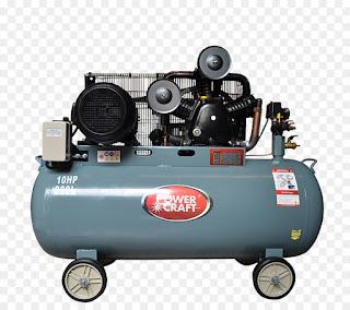
 injection moulding machine process

Iterative mold development, however, remains considerably a tooling strategy. The difference today is that this is often done virtually with simulation software. But why? Modelling of fluid flow in closed channels has been finished decades. the rationale is within the resins, says Caitlin Tschappat, Moldflow technical specialist with Autodesk and a specialist polymer engineer.


“People don’t realize how complex plastics are and the way they don’t behave like metals. They flow by non-Newtonian principles, with very different flow properties. for instance , they’re highly shear sensitive. It’s complex. many of us check out an easy part and think ‘oh, that’ll be easy to fill.’ that straight forward shape might be one among the toughest parts to manufacture due to many considerations, like warpage,” she explains.


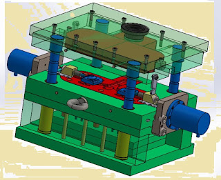
At its simplest, injection molding is about orienting cavities in three-dimensional space with a parting line that permits free ejection of the cooled, solid resin parts. Simply determining the situation of the parting line are often nontrivial. Parts with zero or negative draft angles could also be impossible to eject with conventional ejector pins, forcing a designer to use fewer cavities, or non optimal cavity orientation during a mold to urge clean ejection. In some severe cases, there's no thanks to orient the part to facilitate ejection, and core pulls must be used, adding complexity and price .

 injection molding machine working

The complexity doesn’t end there. Co-injection, over molding—especially of TPU’s over commodity thermoplastics—and in-mold decorating all complicate the mold design process.


If very high-volume production is important, like within the packaging industry, stack molds may require complex designs with multiple parting lines and a requirement for fast, clean ejection. Symmetry helps, and a 64 or 128-cavity small part mold could also be an easy matter of design recursion. A family mold, however, or parts that need special features like the favored “living hinge,” are often very difficult to style. There also are multiple other issues involving gates, runners and other essential mold features.


The advantages of simulation are obvious. Tschappat is an industry veteran with experience within the packaging and automotive industries and has seen this complexity up close.

“Think a few larger part,” she says. “The automotive industry, for instance, has many long, thin parts. For these, you want to consider the ratio with reference to part length to wall thickness, because it would be difficult to fill uniformly without the inclusion of complex runner systems, hot drops and valve gates. On the opposite hand, small parts, like those for medical or electronic applications, can also require an equivalent complexity with reference to the runner systems, as they can also be difficult to fill thanks to small features and limited filling pressures.”

 injection molding machine manufacturers

Modern mold design partially addresses the complexity issue by the utilization of off-the-shelf mold bases, inserts, gates and other standardized components wherever possible. Advanced simulation software like Autodesk Moldflow works with these components to permit accurate approximations of mold performance in gating and cavity filling.


Cavity balance is usually a high priority when filling multi-cavity molds, which may sometimes be remedied through the utilization of mold cavity symmetry. These instances also are ready to simplify mold simulations, like how other Finite Element Analyses use symmetry for model simplification.


For family molds, or large single cavity molds with complex shapes, simulation makes the difference between a productive and cost-effective tool, and a design that's revised such a lot it “goes through the alphabet.”


Before simulation became more widespread, it had been not uncommon to change important mold components on the fly, like quick-fixes to gates for improving mold balance. Unfortunately, these are even as it says—quick-fixes—leading to effects on other aspects like part quality like jetting, knit lines and even dimensional instability. that sort of experimentation may solve a drag , but it frequently requires a complete rethink of the general molding strategy, with new machine parameters which will require many shots to perfect.

 plastic part design for injection molding an introduction pdf

The ability of simulation to attenuate rework not only reduces time spent on the mold, but also the training curve on machine found out with a replacement job. for outlets with a captive press operation, the savings for reduced downtime and improved machine scheduling ability are obvious, except for mold shops there are additional benefits. Rework costs and delivery delays are reduced, customer satisfaction is improved, and therefore the too frequent finger-pointing (who pays for that modification?) are often greatly minimized.

Complexity may be a given with modern injection molding and lots of jobs simply can’t be attempted without advanced simulation. Tschappat describes how she uses Moldflow to deal with higher level problems, saying, “We have many modules within the software counting on what questions you would like answered, whether it's co-injection, two-shot, over-molding or insert molding. for instance , with gas assist, we will help identify where the gas void will settle within the cavity, or with coinjection how two plastics are getting to bond together within the analysis.”


Simulation helps address the previously mentioned topic of cavity balance for multi-cavity tools.

 plastic part design for injection molding malloy pdf

"We see numerous tool cavity layouts when talking with our simulation customers. But the one thing that always seems to throw people off is that if they will escape with molding quality parts from family tools, where each cavity could also be a special part, and technically would wish different processing conditions,” says Tschappat.


“Using Moldflow simulation, we model up the mold layout and predict the part quality of the various cavities. Then we experiment with artificially balancing the filling through the utilization of adjusting runner diameters between cavities or changing the runner design, to aim a more uniform filling from cavity to cavity. albeit the filling is balanced, other factors like shear-induced imbalances can occur as a results of the various geometry features. this is often where simulation is basically cool—seeing something that we will not even see with our eyes when actually molding the parts at the press," she adds.


The types of runners are another source of complexity. Hot runners are standard for volume production thanks to zero or minimal wasted material, but cold runners leave re-purpose of their runner material toward regrind to feature to material savings through reusing small percentages. But as Tschappat observes, “based on your part, what's the simplest gating scheme? counting on how big your part is, maybe you're employing a fan gate, or if it is a smaller part it'd be alittle pin gate. Then the pressures and therefore the pressure drops are an element throughout the runner system. These are all things that make it complex, yet you've got to weigh them out at the top of the day to work out what's best for your business.”


Even a seemingly simple change during a commodity resin can introduce issues. “They teach you in class that if you're getting to be employing a different resin, particularly very dissimilar materials to people who you’re wont to , you ought to build your mold thereto material,” Tschappat says. “We all know that that's not necessarily the practice. you'll start out with a non-filled material then plan to switch to a glass-filled material after manufacturing a couple of shots, for instance . Now you've got to stress about more abrasive decline the tool over time. What does one neutralize those situations? More frequent tool inspections and reworks, maybe even welding up the gate and re-cutting it so it allows for fewer shear of the fibrous material. These kinds of things just take overtime out of the method and slow you down, but it's normal practice.”

 injection molding machine design simulation pdf

The ability to rerun a simulation with a replacement material virtually can flag a molder about potential problems before they translate to expensive tool rework and downtime. Warpage is another common reason for modifications to the tool design. an honest designer who has familiarity with simulation packages like Moldflow can gain insight into root causes of those problems.


“Once you actually get comfortable, you'll actually isolate causes of the warpage to raised understand why something is warping,” states Tschappat. “For example, if you're getting tons of warpage thanks to a thicker cross-section because your material's not freezing off and you've got tons of shrinkage therein area, Moldflow allows you to ascertain that then make a design change and rerun an analysis to see how that style change reduces overall warpage. this is often why we are working more and more with part designers. they will use simulation as they design the part to flag these problem areas before escalating to the tool designer, resulting in fewer iterating between the 2 , making them appear as if they're superstars!”

 injection moulding machine training

The cooling issue is critical and is usually harder to perfect than the cavity and runner design. Although 3D printing promises truly conformal cooling, most production molds are cooled by drilled and manifolded channels carrying coolant, usually water or oil, which carries the warmth away by the thermalator.


There’s an old rule of thumb that for efficient cooling, set the machine to eject the part at 80 percent of the part’s heat distortion temperature. However, for complex parts, multiple cavities or complexity added by factors like thermoplastic elastomers, coinjection or gas assist, rules of thumb are quickly replaced with empirically derived settings during the mold runoff. Cooling is typically the determining think about overall cycle time, so here time considerably is money.


Simulation of cooling channel layout and flow capability are often equally or more important than efficient cavity filling for a high capacity mold, and within the world of injection molding, only a few molds aren't thought of as high capacity, meaning cooling is nearly always a critical factor.

Mold designers are frequently faced with customer requirements which will be difficult or maybe impossible to realize . Most production shops understand their press plate size and tonnage, chiller capacity and target cycle time, but know little about the mold.

Customer expectations can sometimes be unrealistic. “Part designers and mold engineers need to work with each other ,” says Tschappat. “Time is money, and everything must be finished yesterday. It goes through several phases. How are you getting to lay your model out? you've got to think about where you are going to inject resin and locate your gates. then what sort of gate you are going to use. What sort of runner systems? Is it getting to be a hot manifold or are cold runners getting to be sufficient? Or is it a hot to cold runner? what is the ejection unit look like? Where are you able to squeeze cooling in?”

 injection molding operator training

“Often in my job, you get parts from customers and you ask them, ‘what's your cooling layout look like?’ you'll get a solution thereto question, or they'll not know. Often a designer will just squeeze cooling in there wherever they need extra room left over,” Tschappat adds.


Even the potential of the machines that run the mold are often assessed critically with mold simulation. Simulation allows a mold designer to run “what if” scenarios which will show a customer where expectations are unrealistic and nudge them to a far better mold design without an argument.


Math is definitive. “If you're limited within the types or how large your injection molding machines are, then you're limited to the dimensions of the mold that you simply can put therein unit,” Tschappat says. “And then in fact , what proportion pressure it's getting to fancy fill these parts? is that the machine large enough to not just fill out the cavities, but hold the pressures needed to pack those parts? If it isn't , you are going to possess some problems and you're either getting to need to redesign the tool or reconsider it. Or buy a replacement machine.”


This isn’t a theoretical consideration. Tschappat has seen customers who were spared the value of a replacement machine when shown the advantages of a far better optimized mold design.

 learn injection molding

Does simulation replace the tooling designer?


“No,” declares Tschappat. “I would say there's still an art thereto. When I'm in conversation, I regularly tell people they ought to be using simulation as an additional datum or another datum , and use their experience. This actually ties into that aging workforce, too, as we're beginning to lose that skillset. People are retiring, so how can we build that have base up? Simulation may be a specialized thanks to help. children got to be sponges; if you are a toolmaker or a tool designer, work closely with the older generation to select up a number of their skills.”


Simulation software for injection mold design has progressed from “nice to have” to a “must have” for cost effective tooling

“I think it did wonders for the industry because you are able to create an ROI case and see where you'll improve cost savings at the top of the day. Everybody wants a more complex part cheaper, faster, quicker, and by incorporating this type of technology into your workflows and work processes, we will help achieve that goal for our customers.”

Friday, August 14, 2020

What is the Difference between single screw extruder and twin screw extruder

 Difference between single screw extruder and twin screw extruder

Polymer Extrusion - Single Screw Extruder vs. Twin Screw Extruder


What is the Difference between single screw extruder and twin screw extruder
        Hi friends, today we are discuss about difference between
Polymer Extrusion - Single Screw Extruder vs. Twin Screw Extruder. If you like my article, please share in your groups and follow my site www.automationwale.in


         Polymers are amazing material, but for majority of its application Polymers are mixed with other fillers additives and colorant for better performance and appearance. Performance of these mixed polymers depend on the quality of mixing in plastic industry.

        Single screw extruder and twin screw extruders are the most common machine used to mix polymer and additives. Here we know about basic characteristics of single screw and twin screw extruders and then we discuss about how do they differ from each other?

        Both single and twin screw extruders are consists of some basic elements like screw, feeder, barrel, heating element, motor and gearbox. Single screw extruder contains one screw where as twin screw extruder contains two screws presence of one or two screw significantly changes the flow and Amount of shear that can be applied on the polymer. Extruders mostly contain more than one feeder to achieve desired loading of additives in the polymer.

Difference between single screw and twin screw extruder ppt

        In case of single feeder polymer and additives are pre-mixed. Barrel is a long cylinder which hosts screw and keep molten polymers confined inside the extruder the inner layer of barrel is specifically treated to eliminate any reaction with polymer at high temperature.

       Heaters are mounted on the barrel to melt the polymer and keep it at desired temperature during extrusion. Several heaters are used to separately control the temperature at different zone. Mostly extrusion is performed at 50 ‘C higher temperature than the melting point of polymer. Which has a melting temperature of 165 ‘C And Finally all extruders contain motor and gearbox.

      To generate motion and transfer motion from motor to screw every component of the extruder influences the mixing quality and efficiency  single screw extruders contain one screw the screw mostly is single metallic shaft except Containing flights to guide the polymer inside the barrel most screw contains three distinct sections,

Twin screw extruder working principle


1)    feed section

       In this part flight depth is high so that more amount of plastic blades can fit in As plastic is fed through the hopper it melts and move forward due to back pressure. Back pressure is the most important factor which controls flow of polymer inside single screw extruder.

2)     Compression Section

       In this section the flight depth gradually decreases It allows polymer melt to get compressed and release any volatile material which can be harmful for the polymer.

3)    Metering Section

       In this section flight depth is very narrow Which creates high shear and thus help additive to disperse in the polymer matrix.


      It is important to note that the relative length of each zone Depends on the polymers melting behavior and the viscosity of polymer melt. If polymer are difficult to melt it needs longer feed zone but if polymer possess very low melt viscosity, Then we need to use small feed zone and long compression zone.

      Therefore various types of screw design is available in the market. Pressure inside a single screw extruder is gradually increases from feed zone to metering zone, the increase in pressure is related to decrease in flight depth the pressure also reflects the amount of shear applied in each zone.

what kind of screw elements normally used in screw

      As polymers are always under pressure inside the barrel. We cannot put vent in single screw extruder Because polymer melt will shoot out from the vent recent development in a screw design Have allowed putting vent in the single screw extruder, but it is still not widely adapted.

       Now coming to twins Screw extruder Twin-screw is much more versatile than single screw extruders presence of two screws allows several variations in terms of rotation, position, and time, Therefore there are several types of twin screw exist in the market Based on rotation Twin-screw can be classified into Co-rotating and counter rotating.

      In case of co-rotating both screw moves in the same direction Where as in counter rotating the screw rotates in opposite direction. For plastic compounding co-rotating twin screw extruders are mostly used. In terms of position Twin screw can be classified into inter Mixing and non intermixing,

      In inter mixing two screws are positioned Very close to each other so that flights of one screw enters in the flight depth of other screw. Arrangement of screw in this way allows self wiping of screws and better transfer of polymer melt from one screw to another screw, In non inter mixing screws are positioned far apart, So that flights do not enters in each other space These types of twin screw are used for high throughput compounding.

      Twin-screw can also be classified by the screw types like single shaft or modular, Single shaft screws are very similar to single screw extruder. Single shaft screws provide option to achieve very high shear. But to process different types of polymer and additives whole screw needs to be changed.

 Twin screw extruder working principle

    The modular screw consists of individual elements arranged on a shaft. As elements can be arranged in a wide number of ways, the screw design can be extremely versatile.

     Most common elements in a twin screw extruders are conveying element, needing block and flow restrictor. Number and location of these elements can be easily changed thus provides huge amount of flexibility during compounding. Needing blocks provides high amount of shear, thus help to achieve excellent dispersion of additives.

      However, if the polymer is sensitive to extensional flow Having needing block can be a problem. Flow restrictors reverses, the flow of polymer milt thus allows additives to mix properly in the polymer matrix. Depending upon the difficulty of dispersion a typical screw obtain, screw extruder will consist of one or more section of kneading and flow restrictor blocks.

Twin screw extruders a basic understanding

     Presents of various types of elements in the screw also leads to different pressure level inside the barrel. Feeding pressure increases as polymer melt moves forward. Highest pressure is developed at kneading block. The pressure again drops as we move to conveying element from the kneading element. Depending upon the offset angle of kneading block different amount of pressure is developed at different kneading block section and almost no pressure is developed at the conveying section.

     Presence of sections with zero pressure allows manufacturers to put extra feeder and vent a different part of the machine. Between screw extruders ability to provide opportunity to have multiple feeders and vents significantly enhances its mixing ability and efficiency, Actually the presence of two screws significantly changes.

      How polymer is processed in twin-screw compared to single screw extruder. The most important differences is in single screw extruder polymer melt flows passively due to back pressure. On the other hand in twin screw extruder there is active flow of polymer melt since polymer melts are actively transferred from one screw to another screw. The active flow of polymer melts provides two very important benefits.

Application of twin screw extruder

        First twin screw extruder can run in a starved mode which means it is not necessary to completely fill twin screw to move material forward But in case of single screw extruder, it is important to flood fed otherwise polymer melt will not move forward.     

       As twin screws are starved fed there is almost no pressure in conveying zone. Another benefit of active melt transfer is that we can control how materials can flow inside the barrel and how long it could stay in a specific segment of the screw.

      There by mixing efficiency can be optimized Overall, it can be said that extremely good mixing efficiency of twin screw extruder can be attributed to presence of high shear elements, vents and active material flows,


Advantages and disadvantages of twin screw extruder

      So, to summarize the difference between the single screw and twin screw extruders We can say that,

       The first difference is number of screws, Single screw extruders contains one screw, where as twin screw extruder contains two screws, The screw of twin screw extruders are mostly modular therefore provides opportunity to design in an infinite number of ways where as screws of most.

      Single screw extruders contents will define three sections so provides little flexibility in screw design as High shear elements are present into in screw extruder It can apply significantly high amount of shear then single screw extruder Modular design and starve feeding in twin screw extruder also allows putting vents and additional feeders at different parts of the machine.

      Overall twin screw extruder provides significantly better mixing efficiency then single screw extruder,

      However initial investment in single screw extruder is significantly low compared to twin screw extruder and single screw extruder is significantly better in processing shear sensitive polymers and additives,

      So, if Additives is compatible and easy to mix single screw extruder is preferred compared to twin screw extruder In summary, we can say that both single and twin screw extruders offer some benefits and both of them have some limitations. Therefore the choice of extruder will depend upon type of polymer and additives.

      Thank you friends ,if you like my article, please share in your groups and follow my site www.automationwale.in


Thursday, August 13, 2020

TYPES OF INJECTION MOLDING MACHINES

TYPES OF INJECTION MOLDING MACHINES


TYPES OF INJECTION MOLDING MACHINES
     Hi friends today, we wii discuss about how many types of injection molding machines are there in the plastic industries. if you not follow my site, please follow my site www.automatiowale.in


         I am going to tell you that injection molding machine are of basically four types, so four types of injection molding machines  are as Use in plastic industries.

1)   Plunger type injection molding

2)    Plunger - Plunger type injection molding

3)    Screw plunger type injection molding

4)   Reciprocating  screw type injection molding


 types of injection molding machine pdf

       So, there are basically four types of injection molding machines.  there are many more like rubber injection, metal injection, a vertical injection these all comes under these categories.

        So, let’s describe about all these types of injection molding,

Plunger type injection molding


      let's starting with a plunger type injection molding you can clearly see the mold, the cavity section and the core section. Now I am going to tell you about the plunger and the hopper. The plunger is just above the hopper so, charge the  raw material inside the hopper is attached with Barrel, which has some band heaters fitted over it.

injection molding equipment

      We set temperature from that controller, close out the mold, fix the mold beneath the nozzle tip, clamp the mold by  gear system by clamping the mold with the gears the plunger will move downward and it will inject the material which has been melted inside the barrel into the mold, this is done with some pressure some high pressure is needed to inject that particular material in the mold.

      this is plunger type injection molding machine because a single plunger is using in this machine, that plunger moves back to its original position after complete the injection process. After that the material charge and the material which has been filled in the mold left for the solidification, it’s also known as cooling, at that particular time the material cools down, After that  open the clamp, open the mold to take out the product.

       It’s a simple method, it's used in small-scale industries for some small products, it's very rare use oftenly these type of machines. it's quite simple method, the complete working of our plunger type injection molding machine

 Screw plunger type injection molding


       Screw plunger type injection molding and plunger- plunger type injection molding are quite common, Both types injection molding  machine in above image, in this type of machine there are two chambers, one chamber is to plasticize the raw material  and another chamber is used for injecting the material inside the mold, so upper section consists of plasticizing chamber in which the hopper is attached the material which is inside the hopper is transmitted in the plasticizing chamber and then the plasticized material will be transmitted to the injection  plunger area (another chamber) then injection plunger will move forward and the material will be filled inside the cavities of the mold.

 injection molding technique

     The screw is rotating and the material which is being plasticized has been accumulated  in the injecting chamber, the mold closed and has been clamped, the material is being charged from the hopper to the barrel in the barrel section there is a screw which is rotating and along with a screw the barrel consists of some band heaters band heaters along with screw  they both helps in plasticizing the raw material this melted raw material move toward another chamber which is called the injection chamber in that injection chamber there is a plunger which moves forward and the raw material which is in melted form is being injected inside the mold.


Plunger-Plunger type injection

    Quite simple similarly the function for plunger-plunger type injection molding machine is same instead of a screw which is in the plasticizing chamber there is a plunger and heaters used for plasticizing  plunger type injection molding machine and a screw plunger type injection molding machine the functions of both the machines are quite similar but the result and efficiency of a screw plunger type machine is more efficient than plunger  type injection molding.

     In plunger type injection molding machine the raw material is plasticizes by heaters the band heaters which are being attached over the barrel and then the plunger moves that raw material into the injection plunger chamber and  then what happened that injection plunger moves forward and  the entire plasticized material is injected inside the mold.


Reciprocating type injection molding machine


       now you can clearly see the heating elements are attached to the barrel, Inside the barrel there is a reciprocating screw, that this is known as a reciprocating screw that's,

      Why the name of machine is called reciprocating screw type injection molding, The  reciprocating screw is divided in three zones which are,

    1)  Feed zone

    2) Transition zone

    3)  Metering zone

     In feed zone the material is transferred from the hopper to the barrel, next is transition zone also known as compression Zone, the material is being compressed and third is metering zone in front of the screw there is an NRV which prevents  back flow of material that it do not return back inside the barrel at the time of injection.

injection molding machine parts and function

    The charging material from hopper to  barrel but while rotating the screw backward the material is being charged And filled  barrel with the plasticized raw material materials are basically in the granules form, after that injection process, before injection close the mold, the mold is being   closed by the clamping system either it is toggle ram or fully electric, the mold is closed mold consists of some cooling system, we cool down the mold with mtc mold temperature controller  or with the water system called cooling tower.

         This is a simple cooling system, inject the plasticized raw material which has been accumulated inside the barrel  inject - material inside the mold simple method the screw will move forward the reciprocating screw will be moving forward and the material  is being accumulated over the tip of the screw,  material is being injected inside the mold this process is done with high pressure.

    This is the most common and efficient machine used in the plastic industries of injection molding the high efficient machine and high earning machine. the screw will move backward at that particular time the dosing will  start dosing means the charging of material from barrel - hopper and then - plasticize that material now the part is being ejected.

    Thank you friends, if you like this article please share in your groups and follow my site www.automationwale.in


Thursday, July 23, 2020

how to determine pulley size for electric motor fan flow rate calculation

how to determine pulley size for electric motor fan flow rate calculation


Fan & motor CALCULATIONS, Pulley size, RPM, air flow cfm hvac rtu


           Hi,friends today we are discuss about how to determine pulley size for electric motor fan flow rate calculation. so ,please read full article for more knowledge.

     
how to determine pulley size for electric motor fan flow rate calculation
        During this Article we're performing some fan calculations and we're see the way to calculate the fan pulley diameter, the motor pulley diameter, the fan revolutions per minute, the motor revolutions per minute and also what the adjusted air flow would be ,if we were to vary these.
             Now, with the fan, if it's already installed, then you'll should get a sheet , which tells you this is often just the planning data. So everything you would like to understand about the fan. we will look today the way to calculate these and fill the blanks in and if you are a designing the ventilation , then we're check out the calculations for a way to truly calculate and enter these values.
             Now, we're be employing a few technical terms today's like fan, motor,pulleys, RPM, etc. so just to bring it up to hurry thereupon Exhaust the fan. we have got the motor, Then we have got the fan. Now these two which are connecting. we have got the belt pulley . So this is often the pulley wheel And another pulley wheel. So one is that the fan pulley wheel and another is that the motor pulley wheel. When the motor spins,obviously that's transfer that rotation over through the belt and into the pulley of the fan. which can rotate that and as that fan begins to spin.
           

pulley rpm formula

       That is what provides and pushes the air off into the building. therefore the rate that the motor spins is understood because the RPM, the revolutions per minute And also the speed that pulley spins is understood because the RPM,revolutions per minute. So we'll have a glance at what size they have to be and the way fast they have to spin so as to realize the proper flow , if you were to vary them, what the air flow change would be the adjusted value .
           Therefore the first one we're getting to calculating the fan pulley diameter. we've the metric and imperial calculations on here And we have got a formula over here . I find it just makes it tons easier to follow the numbers but the formula we'd like for this , 
           The fan pulley diameter is adequate to the motor pulley diameter multiplied by the division of the motor RPM divided by the fan RPM and that we got some data within the calculations . So we will get these figures from the manufacturer if you haven't already purchased the equipment then you'll look it up online and you'll see what the RPM is be for these fans and motors.

         
pulley size vs rpm calculator

         For the fan, that's be the RPM you would like to supply x amount of ventilation or air flow and therefore the motive the RPM that it's rotate at. So for the primary one, we have got a 95 mm diameter pulley on the motor pulley diameter. So, there's 95 mm across or 3.74 inches and that we know that the motor is rotating at 2861 RPM. Same for the Imperial then the fan so as to realize the air flow that we'd like , it's gonna be rotating at 3020 RPM. Same for the imperial.
          So if we do the division first then you will see , we get but one where it's 0.94735% and it is a percent because ,we're doing a division of an equivalent units, so, it becomes a ratio so it is a percent. Then we have got 95 mm multiplied by that percent equals 90 mm or 3.54 inches ,so the fan pulley diameter, that must be having a diameter of 90 mm so as to realize a design that we'd like . 
          Now differently to calculate this, if we were to possess slowed the motor down. We've changed the flow that we'd like servicing the ground . half the ground is cleared out and that we make some energy savings or change the planning data, then we will use this formula here. 
      

cfm calculation formula


         Therefore the new fan pulley diameter is adequate to the old fan pulley diameter, multiplied by the old air flow , divided by the new air flow . So for this though, just put during a 10% reduction from the first from the planning data. And if we punch those numbers in, then we will use that for the imperial side also . Doing the division,obviously cancels that out and makes that that a percentage for a ratio. So it's 1.11%. Multiply that by the first fan pulley diameter which lets us know that the new diameter must be 100 mm or 3.93 inches.
       Therefore the next thing we will calculate is that the motor pulley diameter. Now there might be various reasons why this has changed. there is a new motor being replaced, a replacement fan has are available so you would like to understand what diameter that pulley must be to realize that correct air flow . 

fan flow rate calculation

         For that we'll use this formula here. therefore the motor pulley diameter is adequate to the fan pulley diameter, multiplied by the fan revolutions per minute, divided by the motor revolutions per minute. Again, you'll get this information from the manufacturer or from the designer, if it's already installed. So if we just drop the numbers in. So on the fan, we've a 90 mm diameter pulley or 3.54 inches and we'll do the division between the 2 RPM's, canceling out the RPM's 
 leaving us with 1.056%. Multiply that by the fan pulley diameter which gives us what the motor pulley diameter must be which is 95 mm or 3.74 inches. 
         Differently to try to to this, if we all know there has been a change within the flow and that we got to know what the change in diameter for the pulley are going to be on the motor, then we will use this formula here, which is that the new pulley diameter is adequate to the old motor pulley diameter, multiplied by the new air flow divided by the old air flow . 
        Now we all know what the old air flow is and therefore the diameter of the pulley. this could be the new air flow and you'll calculate otherwise you can take it from the new manufacturer , But if we drop these numbers in then obviously these will wipe out on each side . in order that will give us a percent again and that we can see that the first pulley diameter multiplied by that percent is equal now to 85 mm or 3.73 inches. that is the new motor pulley diameter. 
       So then we will check out what the fan RPM must be so as to realize our criterion . for that we'll use this formula here which is that the fan RPM is adequate to the motor RPM, multiplied and that we already know these figures. We should've calculated them or taken them from the manufacturer of any new equipment or from the planning data. So if we drop the numbers in, then obviously we'll get right down to a ratio again if we do a division of the pulley diameters then we will multiply these together which will bring us to 3020 RPM on both metric and imperial because is that the "> it is the same units there which is the speed that the fan needs rotate at to realize the planning in flow .
       Now we will also calculate the motor RPM and that we do this using that formula here. therefore the motor revolutions per minute, equals the fan pulley diameter multiplied by the fan revolutions per minute, divided by motor pulley diameter. so, we will drop those numbers there in and this may then begin at 2861 RPM on each side , Imperial and metric.
      Again you'll just calculate these or look them up from the manufacturers. Now if you've got made any changes to the fans and therefore the motors, then we would like to understand what the adjusted air flow are going to be and can it satisfy the planning criteria or are we making the reduction so as to scale back the air flow to form some energy savings? And if that is the case then we will use this formula here therefore the new air flow is adequate to the old air flow multiplied by the division of the fan RPM. The new divided by the fan RPM of the old.
       So we will then stick these figures here in. So we all know what the old flow was and what they adjusted RPM goes to be and therefore the original RPM's so we'll stick these beat , this may bring us down .so obviously another ratio and that we can multiply that out and that'll bring us to 1.638 meter's cubed per second. There should be a cube Or 3470 cubic feet per minute.
       Okay that's it for this text . many thanks considerably . I hope you've enjoyed and it's helped you. If you've got any questions, please leave them within the comments section below. do not forget to love , subscribe and share and also check on our website https://automationwale.blogspot.com once more , many thanks considerably friends.

Monday, July 20, 2020

How cooling towers works

How cooling towers works


Hi friends,In this Article we're gonna check out the operation of a cooling system . 

  cooling tower diagram 


How cooling towers works
         So even as a fast overview of what to expect from this text we're gonna check out the operation of the cooling system here And we're gonna check out how the nice and cozy water, which is being sent from the chiller and contains the warmth from the building, which must be rejected.
    (cooling tower basics)That's getting to enter the header undergo this spray nozzle and be distributed over this packaging. That warm water will then loose a number of it's heat because it makes it's thanks to rock bottom here. it'll drip down and then collect into the basin and therefore the cooler condenser water is then collected from the basin sent backtrack to the chiller, where it'll devour that heat again and be sent up during a continuous loop there. cooling tower definition
 

 cooling tower basics  


    cooling tower power plant ,which humid air, you know it's lost some humidity here; that's then rejected by this fan and pushed out into the atmosphere. We're gonna check out each part of this in far more detail, Cooler towers, but these are really used on every single building, large building. Just the sort of cooling tower will change.      Some are going to be kind of open wet cooling towers and a few won't. It all depends on the planning criteria. we have got a touch model of a cooling system. during a world example of one among these sorts of cooling towers. We're gonna run through how one among these works and what it's used for. So in building services these are used on almost every single office block round the world counting on it's size. 
         (cooling tower diagram) Meanwhile cooler air /ambient air is being sucked in to the present cooling system . That passes within the opposite direction of the condenser water which picks up the warmth from the water. But because it does that it'll also devour a number of the water making this very humid and really moist. So we have got this drift eliminator at the highest here which will condense a number of that water so we will reclaim it and keep our operating expense down. 
       induced draft cooling tower   They're very effective at rejecting heat. So what happens is; you employ these to reject the warmth from the building. So all the warmth gets picked up from people, computers, machines,lighting, all the solar gain, all of that heat needs to be faraway from the building to stay it cool. So that's picked up by a chiller and it's sent from the condenser up into ones of those , which may be a cooling system . and therefore the purpose of this plant item here is to require water in at a particular temperature and put it back to the building at a way lower temperature in order that it can devour more heat again and send it back to be chucked out of the unit.
       So let's have check out some of the components in there. you will see on the highest we have got a lover . So this fan obviously spins and because it does so it pulls air out of the unit. Air flows in, fresh air, ambient air, air around you flows in from the panels, which it just filters. they have an inlet shield just to prevent sunlight and mud and bugs, maybe animals, even children getting into there. (laughing) therefore the air comes into now here then makes it's way up and gets pulled out of the cooling system at the highest here. And on the surface we have got a motor here And on this instance I've just made an easy belt drive system which pulls that fan. 
     application of cooling tower  But the motor might be mounted inside or it might be a gear ratio or something. But we're just keeping it very simple on this one, so I've put a belt system on there and truly let's have a look inside the unit here. So, this is often a peek inside the unit. And as you'll see we've got some pipes here with some funny looking plastic parts here and here. A couple of other little pipes, let's just change view there. So, the condenser water which is that the warm water that's being collected from the building and being sent up by the chiller, that enters through this pipe and it enters into the header which warm water is then sprayed out of those spray nozzles
     cooling tower , Within the world the spray nozzles coming down onto the packaging will look a touch. So these nozzles here quite this and they are just spraying down across the fill packaging. On to the present which is understood as the packaging or the fill. within the world the packaging will look something and therefore the purpose of this fill is that the water, the condenser water will run because it sprays in really fine particles and it collects and runs down the sides of this during a thin film. 
      Now the air which is rushing past the opposite way picks up heat from this because if you let it just quite run out then it's got a little area , but if you spread it out and convey the really thin film, across of these packaging sheets, which is formed of a kind of plastic then that increases the area . then you're maximizing the world that the air can reach or can touch. then once it does that it pulls the warmth out of that water. The water, the condenser water will then avalanche the side here and drip down and collect down here within the basin. 
     which warm air will enter through the sides or these panels, make it'sway up through these grills or the fill packaging,past this pipe work, up out through the drift eliminators, then out through the highest . As that water pours out of the pipe work and it sprays and becomes a skinny film along this fill packaging here what we're gonna find is that a number of the water will evaporate, which takes a number of the warmth away. But we're gonna lose moisture thereto also .
         Therefore the purpose of this which is called the fill packaging. No it isn't sorry it's called the drift eliminator. What happens is that the air enters into here, it's being pulled by the fan at the highest here and therefore the air is coming in at a high velocity and it's impacting, it'shitting against the surfaces. It's gonna make these really sharp turns to urge out of the system and obtain to where the fan is trying to pull it out through. So because it does this and it's colliding with the edges and that is giving the moisture within the air an opportunity to condense on the sides then run down.
       Therefore the more impact it makes the more it's condensing that vapor within the air and allowing it to condense and pour away. So we'll reclaim a number of that water, which might otherwise have lost and be sent bent the atmosphere. Down within the basin here we have got variety of pipes. We'll  the most important pipe here. It's a few six inch pipe and that's the outlet. So this is often the condenser water return, which is gonna go back down into the building and right down to the condenser of the chiller. up here we have got the water inlet which is connected to a valve . So because the water level gets too low this may allow more water to enter the tower. And keep this filled to a particular level. 
          Here we have got the over flow. So say this was to possess got stuck, something like the water would pour in here to fill it up, but there is no where for that to travel and you do not want it to refill and begin browsing the tower out the edges here. So we have got an overflow here. Just to require a number of that flow off . 
         The last part here we've got is that the drain. therefore the drain is sort of important because within the water that's entering this tower here, the water contains salts and bacteria and stuff like that and as this water evaporates it's gonna leave behind that salt and therefore the gunk and muck that's contained within the water. which salt won't evaporate. which will start to collect up here within the basin or abreast of the fill packaging etc. then once it reaches a particular level this may got to drain, therefore the cooling system are going to be told to dump tons of the water that's during this tower right down to drain while they add water . Not through that one,sorry through this one. They add water to the system in through here or through the condenser water inlet there. And once that has reached a particular amount of parts per million the minimum threshold, that drain will close and it'll continue init's cycle of operation. and that is really it for a cooling system . Well for this sort of induced draft open cooling system . 

Saturday, July 18, 2020

Compressor - Types of Compressor - Compressor Types

      Compressor - Types of Compressor - Compressor Types        

air compressor types - air compressor -industrial air compressor

There are mainly 5 sorts of compressor that are normally utilized in our industry.

A compressor may be a robot that increases the pressure of a gas or air by reducing its volume. Compressors are almost like pumps: both increase the pressure on a fluid and both can transport the fluid through a pipe. As air or gases are compressible, the compressor also reduces the quantity of an air or gas. during this article we'll see the various sorts of compressor. 

Compressor - Types of Compressor - Compressor Types 


 1. Reciprocating Compressor. (reciprocating air compressor)

 2. Rotary Compressor. (rotary screw compressor)

 3. Scroll compressor. (scroll compressor)

 4. Screw Compressor. (screw compressor)

 5. Centrifugal compressor.  (Centrifugal compressor)


 1)  Reciprocating Compressor 

(reciprocating air compressor)

          
         Reciprocating compressors use piston driven by a crankshaft. they will be either stationary or portable,can be single or multi-staged, and may be driven by electric motors or combustion engines


 2) Rotary Compressor

 (rotary screw compressor)

 These compressors aren't of reciprocating nature, therefore doesn't have any pistons and crankshaft. Instead, these compressors have screws, vanes,scrolls, and other devices which rotate and thus compress air or gas. The rotary compressor are often divided into two types. 
  •        One has blades or vanes that rotate with the shaft.
  •        The opposite type has the blade which remains stationary and is a component of the compressor housing assembly

 3)Scroll Compressor. 

(scroll compressor)

         A scroll compressor has one fixed scroll which remains stationary and another moving or orbiting scroll that rotates through the utilization of swing link. When this happens, the pockets of air or gas between the 2 scroll are slowly pushed to the middle of the 2 scrolls, causing the reduction of the quantity of the air or gas. 

 4)Screw Compressor. 

 (screw compressor)


      The screw compressor uses a pair of helical rotors, where it traps and compresses the air or gas, because the rotors revolve within the cylinder. The male rotor and therefore the female rotor are built inside the cylinder. 

 5) Centrifugal Compressor. 

(Centrifugal compressor)


       Centrifugal compressor is typically utilized in large capacity of compression system. during this compressor, the air or gas is moved during a circular motion that referred to as force . An impeller which may be a disk with radial blades spins rapidly inside this housing causing the gas to realize velocity. 

         Dear friends , Thanks for reading the article any question write within the comment box. do not forget to  share.